PID Control Components
Highly Visible Color Graphic LCD Intuitive Touch Panel Operation
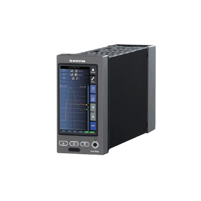
Multi-Function PID Controller SC Series
 SC Series Controllers Controllers with Manual Loader
Model SC100 Basic version 
Model SC110 Basic version Model SC200 Modbus/NestBus extension Model SC210 Modbus/NestBus extension New Generation of Programmable PID Controllers Ideal for Replacing Existing Instruments 
Large fine color graphic LCD
(4.3-inch TFT, 256 colors, 480 x 272 pixels)
IEC/DIN format *1 panel cutout size
(W72 x H144 mm)Intuitive touch panel operation Fully compatible in functions with existing PID controllers DCS in instrument format
Advanced computation and sequential control functions
Easy setting of various engineering functions High Reliability for Demanding Process Use Excellent Expandability (SC200/210) Control, display and I/O functions are managed by
independent CPUs for enhanced security and reliability.Host communication via Modbus
(Ethernet TCP/IP or RS-485 RTU)Built-in manual loader is available with models SC110 and SC210. Peer-to-peer communication via NestBus to expand number of I/Os Stored trend data exportable to a PC via the
built-in infrared communication port *2*1. IEC 61354 (DIN 43700)
*2. PC Configurator SCCFG is used to convert and export data into CSV format.Product Profile
*1 Separetely purchased. Single Loop Controller Series SC Series Controllers Controllers with Manual LoaderModel SC100 Basic version Model SC110 Basic version Model SC200 Modbus/NestBus extension Model SC210 Modbus/NestBus extension AccessoriesModel SFEW3E Loop Configuration Builder 
Model SCCFG PC Configurator Software 
Model COP-IRDA IrDA Communication Adaptor Operation Views - Ease and Continuity
Four types of operation views, Short Trend, Digital Display, Bargraph and Dual Bargraph, are available to suit various process applications, designed for the sense of ease and continuity for the operators who have been familiar with existing controllers.
Short Trend Bargraph 
Loop control parameters (PV, SP and MV) are indicated with bargraphs and on the digital displays. Specific internal computation values can be assigned to FN1...FN4 and indicated on the digital display. 200 samples for four variables per loop are plotted on the chart (total 8 variables). Sampling interval is selectable between 1 second and 60 minutes.
Max. 400 samples of stored trend data can be exported to a PC in CSV format (SC200/210).Digital Display Dual Bargraph 
Loop control parameters (PV, SP and MV) are indicated on the digital displays. Specific internal computation values can be assigned to FN1...FN4 and indicated also on the digital displays. An error message appears in case of an error. Loop control parameters (PV, SP and MV) for two loops are indicated with bargraphs and on the digital displays. Touching 1st/2nd button switches the loop to be manually controlled. Engineering Views - Versatility and Flexibility
PID parameter setting, display and operation setting and function block setting are accessible respectively at Tuning, Configuration and Programming views.
Tuning Programming 
PID parameters, PB (proportional band), Ti (integral time) and Td (derivative time), are set on the Tuning View.
Auto-tuning is also available in this view. Bargraph and digital displays for the loop parameters and the short trend graph are displayed at once.Function block parameters are set on the Programming View by simulating operations of the PU-2A Programming Unit. The SFEW3E Loop Configuration Builder software for Windows PC is also available for ease of setting all advanced function block configurations. Configuration User's Parameter Table Realtime I/O Monitoring 
User's selected parameters are listed, monitored and changed. I/O values and error status of all field terminal blocks are displayed. Display and operation of the Controller are thoroughly adjustable to enhance the user's comfort. DCS in Instrument Format
- Advanced Computation and Sequential Control FunctionsThe control and computation functions are achieved by combining a wide variety of basic to advanced function blocks, which are normally found only in DCS systems. 2 PID blocks, 48 computation blocks and 12 sequential control blocks (1068 commands) are available for all versions of the SC Series, applicable to a wide range of application fields.
 Function Block List
Function Block Structure 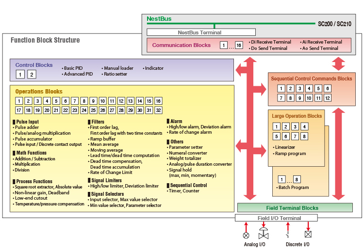
Excellent Expandability - Peer-to-peer and Host Communication
The SC200/SC210 has Modbus (Ethernet TCP/IP or RS-485 RTU) which enables easy connection to logging or SCADA systems on a host PC for supervising and controlling the local I/O data.
In addition, the RS-485 'NestBus' enables peer-to-peer communication with other controllers and I/O devices for flexibility of I/O points.Expanded System Configuration Example 
Single Loop Controller Series SC Series Controllers Controllers with Manual LoaderModel SC100 Basic version Model SC110 Basic version Model SC200 Modbus/NestBus extension Model SC210 Modbus/NestBus extension Remote I/O ModuleModel SML Remote I/O Module (for NestBus use) Application Examples
 Ratio with cross-limiting override control Three-element boiler drum level control
Others Chemical Injection Control Reactor Temperature Control 
The SC100 controls two flow loops for water and injected chemical. The chemical flow is controlled in a constant ratio against the water flow. Other signals from pH and conductivity analyzers can be monitored at once. An example of temperature control in a batch control reactor. The reactor temperature control loop is connected in cascade to the hot water control loop in the hot water tank. The secondary loop controller controls the valves for hot water and steam. High Reliability - For Demanding Process Use
Control, display and I/O functions are managed by independent CPUs for enhanced security and reliability.
The built-in manual loader (SC110/210 option) can be controlled independently even in case of a failure of the main controller module, which can be replaced easily while the backup control is maintained.•
The main module can be disconnected from the backup module and extracted with the front display.
•
The front blue LEDs are connected to the backup module, while the front UP/DOWN control buttons are connected to both main and backup in parallel.
•
The backup module can be powered independently from that of the main module for further reliability.
•
When the control is switched to the backup module either manually or automatically, the MV 2 selector SW is set from Main to Backup.
Backup Function Diagram 
*Independent power supply is optional.•
Transition of output level is smooth as the backup module has been continuously tracking the control module output in normal status.
•
A preset value can be provided also as output in the backup mode.
•
The control module output can be tracked either manually or automatically to that of the backup before switching back to the normal mode.