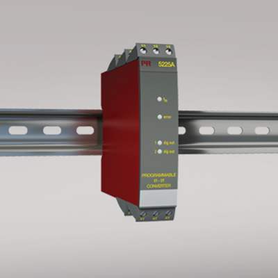
5225
Programmable f/I-f/f converter
- Pulse conditioning
- Frequency generator
- Concurrent f/I and f/f function
- Analog current and voltage output
- PNP / NPN output, optional relays
- Programmable by PC and Loop Link
Manuals : 
Data sheet :
Advanced features
- The 5225 transmitter can be configured with a standard PC and the Loop Link communications unit, or delivered fully configured.
Application
- The f/I function performs frequency to current and voltage conversion.
- The f/f function can be used for pulse division or multiplication and as a buffer collecting fast pulse trains.
- The concurrent f/I and f/f functions enable a scaled digital output signal in conjunction with the analog output.
- The frequency generator function is used as e.g. a time base or clock generator.
- Input and supply polarity reversal protection.
- Current and voltage output signals galvanically separated from the supply and the inputs.
- Programmable digital outputs including NPN, PNP or relay options.
Technical characteristics
- 4 front LEDs, indicating f in active inputs (not NPN), Dig.out.1 (NPN or relay 1) and Dig.out 2 (relay 2) outputs, and a NAMUR input error signal.
- Analog current output can be configured to any current within 0...20 mA range.
- Voltage output range is selectable between 0...10 VDC and 0...1 VDC by use of internal jumpers.
- Programming can be performed with or without a power supply.
Environmental Conditions
Specifications range -20°C to +60°C Calibration temperature 20...28°C Relative humidity < 95% RH (non-cond.) Protection degree IP20 Mechanical specifications
Dimensions (HxWxD) 109 x 23.5 x 130 mm Weight approx. 190 g DIN rail type DIN 46277 Wire size 1 x 2.5 mm2 stranded wire Screw terminal torque 0.5 Nm Common specifications
Supply voltage 19.2...28.8 VDC Max. power consumption 3.5 W Internal consumption 1.7 W Warm-up time 30 s Power-up delay 0...999 s Communications interface Loop Link Signal / noise ratio Min. 60 dB Response time, analog < 60 ms + period Response time, digital output < 50 ms + period Response time, concurrent f/I and f/f < 80 ms + period Signal dynamics, output 16 bit Effect of supply voltage change < ±0.002% of span / %V Auxiliary voltage: NAMUR supply 8.3 VDC ±0.5 VDC / 8 mA S0 supply 17 VDC / 20 mA NPN / PNP supply 17 VDC / 20 mA Special supply (programmable) 5...17 VDC / 20 mA Temperature coefficient < ±0.01% of span / °C Linearity error < 0.1% of span EMC immunity influence < ±0.5% Input specifications
Max. offset 90% of selected max. frequency Measurement range 0...20 kHz Min. measurement range 0.001 Hz Low cut-off frequency 0.001 Hz Max. frequency, with input filter ON 50 Hz Min. period time with input filter ON 20 ms Input types NAMUR acc. to DIN 19234 Tacho
NPN / PNP
TTL
S0 acc. to DIN 43864Output specifications
Max. offset 50% of selected max. value Current output: Signal range 0...20 mA Min. signal range 5 mA Updating time 20 ms 40 ms for concurrent f/I and f/f Load (max.) 20 mA/600 Ω/12 VDC Load stability, current output ≤0.01% of span / 100 Ω Current limit < 23 mA Voltage output through internal shunt See manual for details Other output types Active outputs (NPN / PNP) f/f converter output
Frequency generatorRelay output: Max. switching frequency 20 Hz Relay output: Isolation, test / working 3.75 kVAC / 250 VAC Max. voltage 250 VRMS Max. current 2 AAC Max. AC power 500 VA Max. load at 24 VDC 1 A *of span = of the presently selected range Approvals
EMC EN 61326-1 LVD 2006/95/EC EN 61010-1 PELV/SELV IEC 364-4-41 and EN 60742 EAC TR-CU 020/2011 EN 61326-1