5335A
2-wire transmitter with HART® protocol
- RTD, TC, Ohm, or mV input
- Extremely high measurement accuracy
- HART® 5 protocol
- Programmable sensor error value
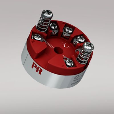
- For DIN form B sensor head mounting
Manuals : 
Data sheet :
Application
- Linearized temperature measurement with Pt100...Pt1000, Ni100...Ni1000, or TC sensor.
- Difference or average temperature measurement of 2 resistance or TC sensors.
- Conversion of linear resistance variation to a standard analog current signal, for instance from valves or Ohmic level sensors.
- Amplification of a bipolar mV signal to a standard 4...20 mA current signal.
- Connection of up to 15 transmitters to a digital 2-wire signal with HART® communication.
Technical characteristics
- Within a few seconds the user can program PR5335A to measure temperatures within all ranges defined by the norms.
- The RTD and resistance inputs have cable compensation for 2-, 3- and 4-wire connection.
- The 5335A has been designed according to strict safety requirements and is therefore suitable for application in SIL 2 installations.
- Continuous check of vital stored data for safety reasons.
- Sensor error detection according to the guidelines in NAMUR NE89.
Mounting / installation
- For DIN form B sensor head or DIN rail mounting with the PR fitting type 8421.
Environmental Conditions
Specifications range -40°C to +85°C Calibration temperature 20...28°C Relative humidity < 95% RH (non-cond.) Protection degree (encl./terminal) IP68 / IP00 Mechanical specifications
Dimensions Ø 44 x 20.2 mm Weight approx. 50 g Wire size 1 x 1.5 mm2 stranded wire Screw terminal torque 0.4 Nm Vibration IEC 60068-2-6 : 2007 Vibration: 2...25 Hz ±1.6 mm Vibration: 25...100 Hz ±4 g Common specifications
Supply voltage 8.0...35 VDC Isolation voltage, test / working 1.5 kVAC / 50 VAC Warm-up time 30 s Communications interface Loop Link & HART® Signal / noise ratio Min. 60 dB Accuracy Better than 0.05% of selected range Response time (programmable) 1...60 s Signal dynamics, input 22 bit Signal dynamics, output 16 bit Effect of supply voltage change < 0.005% of span / VDC EMC immunity influence < ±0.1% of span Extended EMC immunity: NAMUR NE 21, A criterion, burst < ±1% of span Input specifications
Max. offset 50% of selected max. value RTD input Pt100, Ni100, lin. R Cable resistance per wire (max.), RTD 5 Ω (up to 50 Ω per wire is possible with reduced measurement accuracy) Sensor current, RTD Nom. 0.2 mA Effect of sensor cable resistance (3-/4-wire), RTD < 0.002 Ω / Ω Sensor error detection, RTD Yes TC input: Thermocouple type B, E, J, K, L, N, R, S, T, U, W3, W5 Cold junction compensation (CJC) < ±1.0°C Sensor error detection, TC Yes Sensor error current: When detecting / else Nom. 33 μA / 0 μA Voltage input: Measurement range -800...+800 mV Min. measurement range (span), voltage input 2.5 mV Input resistance, voltage input 10 MΩ Output specifications
Current output: Signal range 4…20 mA Min. signal range 16 mA Load resistance, current output ≤ (Vsupply - 8) / 0.023 [Ω] Load stability, current output ≤0.01% of span / 100 Ω Sensor error indication, current output Programmable 3.5…23 mA NAMUR NE 43 Upscale/Downscale 23 mA / 3.5 mA *of span = of the presently selected range Approvals
EMC EN 61326-1 ATEX 2004/108/EC KEMA 03ATEX1508 X IECEx KEM 10.0083X INMETRO NCC 12.0844 X EAC TR-CU 020/2011 EN 61326-1 DNV Marine Stand. f. Certific. No. 2.4 SIL Hardware assessed for use in SIL applications